
Vacuum Controller (Etron) - VCE-100
Setup Instructions:
Quick start guide:
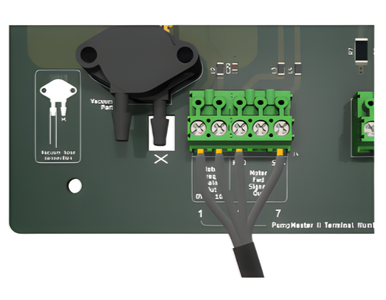
Low voltage wiring:
Pin 1 (Analog Ground) should connect to the analog ground of the VFD
Pin 2 (0-10V) should connect to the analog external reference pin on the VFD
Pin 3 (Motor Forward Switch 1) should connect to the “Start” or “Forward” pin of the VFD
Pin 7 (Motor Forward Switch 2) should connect to the 24V or common pin of the VFD
Pins 3 and 7 provide a solid-state dry contact as a start signal to the motor. These pins are electrically isolated from the rest. The maximum voltage rating across these pins is 35V. They can be used in a source or sink configuration. The length of the low-voltage cable should be kept as short as possible.
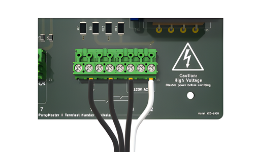
High voltage wiring:
Normal pin connections:
Pin 16 (Wash) should connect to the 120V power through the “Wash” switch
Pin 18 (Run) should connect to the 120V p
ower through the “Run” switch
Pin 20 (Line) should connect to the 120V power line directly for constant power
Pin 22 (Neutral) should connect to the 120V neutral line directly
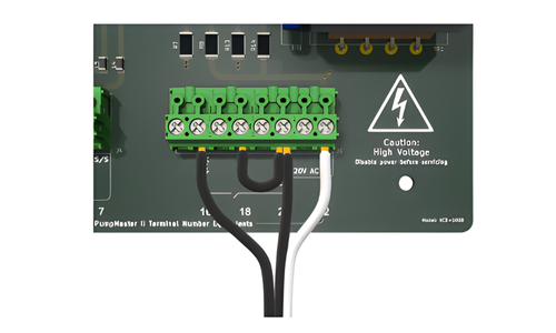
Alternate - When the Run is supplied by the power:
Pin 16 (Wash) should connect to the 120V power through the “Wash” switch.
Pin 18 (Run) should connect to the 120V power through a jumper when power is used as the “Run” or “Milk” signal
Pin 20 (Line) should connect to the 120V power line through the “Run” switch when power is used as the “Run” or “Milk” signal
Pin 22 (Neutral) should connect to the 120V neutral line directly
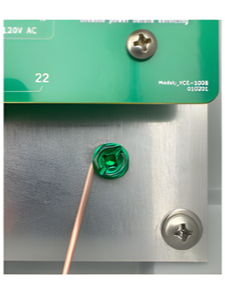
Bond the power safety ground to the back plate:
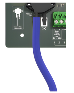
Tubing:
Attach a flexible vacuum level sense hose to the left nipple of the vacuum port. The hose must have an inner diameter of no more than 0.19”.
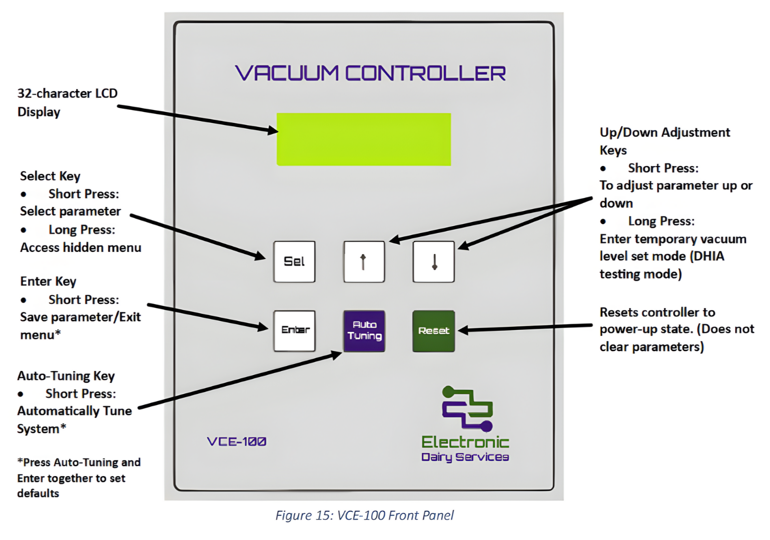
Front Panel: